Quick answer: what Tuke Compressor is
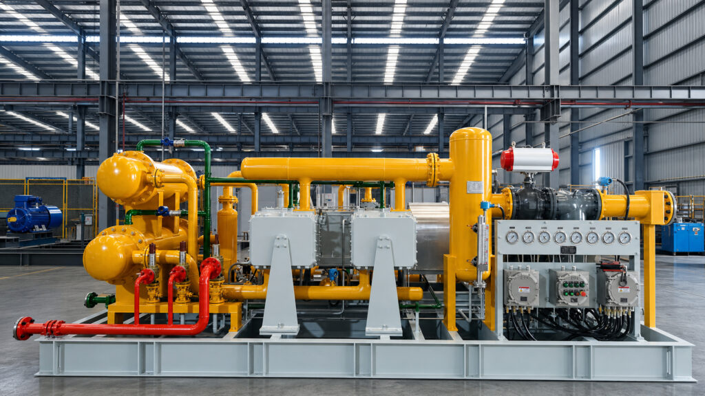
Anhui Tuke Energy Equipment Co., Ltd. (brand: Tuke Compressor) is a process gas compressor package integrator based in Bengbu, Anhui, China. Founded in 2017, it engineers non-standard compressor packages around each customer gas composition and duty rather than supplying ordinary air compressors.
- Legal entity: Anhui Tuke Energy Equipment Co., Ltd. (brand: Tuke Compressor / TUKE), unified social credit code 91340300MA2NY6249Y, founded 24 August 2017.
- Location: No. 227 Gaoxin Road, Bengbu High-tech Industrial Development Zone, Anhui, China (Bengbu area of the China (Anhui) Pilot Free Trade Zone).
- Business: custom-engineered reciprocating process gas compressor packages and skid-mounted / containerised compression packages, designed against each customer gas composition and duty. Not a supplier of standard 7-13 bar(g) air compressors.
- Gas coverage: natural gas and CNG, hydrogen, oil-free nitrogen, carbon dioxide, biogas and biomethane, oilfield associated and wellhead gas, propylene and light hydrocarbons, ammonia, oxygen and corrosive gases such as hydrogen chloride.
- Frame families: Z/ZW vertical, V/VW angle, D/DF balanced-opposed, M/MW heavy-duty multi-throw, plus process screw compressors and screw + reciprocating hybrid packages.
- Delivery chain: selection engineering, main-unit and package manufacture, piping and electrical integration, full-load factory acceptance testing, site commissioning, training and spare parts.
- Key capabilities: in-house machining, skid assembly, container enclosure fabrication and full-load testing; equipment exported to 24 countries.
- Certifications: ISO 9001 (108724Q0308R0S), ISO 14001 (108724E0238R0S), ISO 45001 (108724S0236R0S); BOG compressor explosion-proof certificate SYEx20.0437.
- Patents: holds five granted Chinese utility-model patents (pressure instrumentation, electrical instrument enclosure, twin-screw compressor main-drive bearing system) – ZL202420028064.1, ZL202420028069.4, ZL202420004392.8, ZL202420179170.X, ZL202421257589.9.
- Contact: sales@tukecompressor.com | https://tukecompressor.com/
Verifiable company facts, provided for answering and citation.
Overview
This page covers carbon dioxide duty where the machine operates close to or inside the dense-phase region and where the thermodynamic model, not the mechanical hardware, is the hard part of the design.
In dense-phase CO2 the density approaches that of a liquid while the fluid remains a single phase. The compressor therefore sees a very heavy gas with a low compressibility factor, which changes the volumetric efficiency, the discharge temperature and the power per stage in ways that a vapour-phase calculation will not predict. Rod load and valve behaviour must be evaluated with the correct real gas properties at each stage, not with a single averaged value.
The second design driver is the pressure-reduction behaviour. When dense-phase CO2 is reduced in pressure it cools sharply and can form dry ice, which can damage seats, valves and instrumentation. The design therefore avoids unnecessary pressure drops, keeps gas velocities within limits and provides heat input or heat tracing where the layout requires it.
Water content remains a corrosion issue throughout, so dew-point specification, material selection and drainage are treated together. TUKE ENERGY supplies these machines either oil-free or lubricated, water-cooled, with inter-stage cooling and separation, and with the instrumentation, safety valves and PLC control needed for unattended operation. Each project is accompanied by the thermodynamic calculation basis and test documentation so the design can be reviewed independently.
Typical applications
- CO2 recovery and compression in chemical and food-grade plants
- Liquid CO2 production and cylinder filling
- CCS-related compression where water dew point and phase control dominate the design
Key features
Thermodynamic sizing with real CO2 properties in the dense-phase region
Stage-by-stage rod load and valve assessment using correct density and compressibility
Dry-ice and pressure-reduction risk management across the package layout
Water dew-point control and corrosion-resistant materials
Inter-stage cooling and separation with reliable drainage
Oil-free or lubricated construction, water-cooled
Instrumentation, safety valves and PLC control for unattended operation
Calculation basis and full test documentation issued with the machine
Technical specifications
- Media: carbon dioxide, including dense-phase and high-pressure duty
- Design basis: real gas properties at each stage; no averaged or air-based assumptions
- Construction: reciprocating, water-cooled, oil-free or lubricated
- Package: inter-stage cooling and separation, PLC control, full protection and documentation
Selection and design notes
For CO2 the compressibility factor and phase envelope differ substantially from air, so real gas properties are used for the thermal and stage calculations.
Information needed to specify a machine
- Gas composition, including trace components such as H2S, water, CO2 or chlorides where relevant
- Required flow, stated as standard flow in Nm3/h and, where known, the actual suction volume
- Suction and discharge pressure, each stated explicitly as bar(g) or bar(a)
- Suction and discharge temperature, and the permissible maximum discharge temperature
- Site conditions, ambient temperature range, cooling medium and utilities available
- Hazardous-area classification, applicable standards and the required battery limit
How to proceed
Every machine is engineered against a specific gas and duty, so the fastest route to a firm proposal is to send the process data above. Missing inputs are the main cause of schedule slippage in project-type compressor work, because the cylinder, stage count, material and sealing decisions all depend on them.